INVTSolar Anti-reflux Operation Instruction
When encountering situations such as prohibiting or restricting the transmission of electricity to the public grid in some areas, or the power station has not obtained the power sales permit in time, the PV system needs to have an Anti-reflux function.
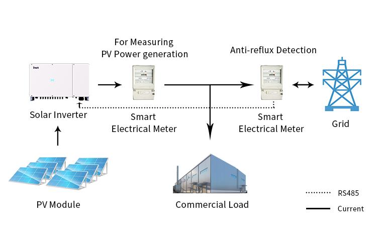
How does the Anti-reflux function work?
The real-time power, current and direction of the line are obtained through the CT/meter installed on the bus on the incoming line side of the house, and the inverter then reads the data collected by the smart meter through RS485, and adjusts the output power through calculation, so that the power and current flowing to the grid are always close to zero. When the PV input power is less than the load demand, the inverter supplies power to the load together with the grid at maximum power; When the PV input power is greater than the load demand, the inverter will perform power adjustment so that the output power matches the load demand.
How to operate the Anti-reflux function?
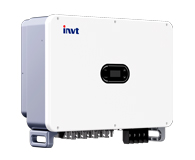
Now, we will show you the operation process by taking XG100-136kW three-phase grid-tied inverter as an example, from the three steps of the wiring of Anti-reflux meter, smart meters setting, and inverter grid connection.
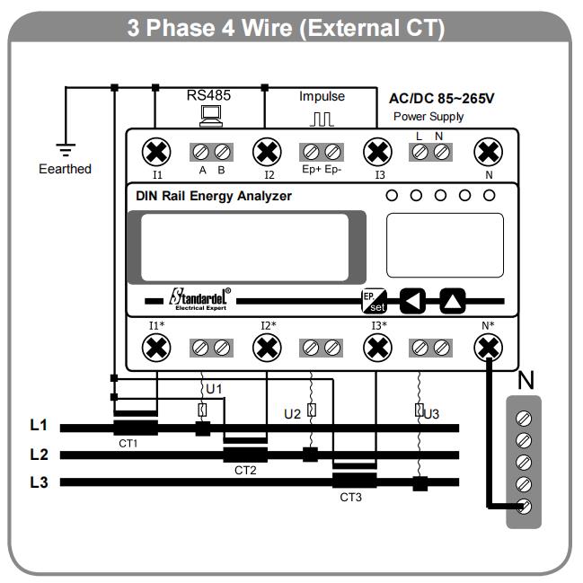
Smart meter wiring (three-phase four-wire system) can be carried out according to the following five steps as shown in the figure:
1、Three CT will be connected to the A, B, and C three-phase grid(Connected to the air switch inlet line end)。
Note: On CT P1 silk screen towards inverter, P2 silk screen towards the grid
2、Connect A phase transformer SI to the smart meter I1* port, B phase transformer S1 to the smart meter I2* port, C phase transformer S1 to the smart meter I3* port; Short-connect A, B, and C transformers S2 to smart meters I1, I2, and I3; N* is connected to the N line of the grid.
3、Connect grid A phase to meter U1, grid B phase to U2, and grid C phase to U3.
4、Take a live wire from any phase of the grid A, B, and C, connect it to the smart meter L, and lead one wire from the neutral line to the smart meter N.
5、Connect one end of 485 line to inverter COM2, take line label 485+ to smart meter A at the other end, and take line label 485 - to connect to smart meter B.
After connecting the above cable to the smart meter, turn on the inverter DC switch and the grid side AC switch.
Step 1 Check smart meter
To check whether the smart meter is normal, whether there is an alarm, and whether the communication is normal.
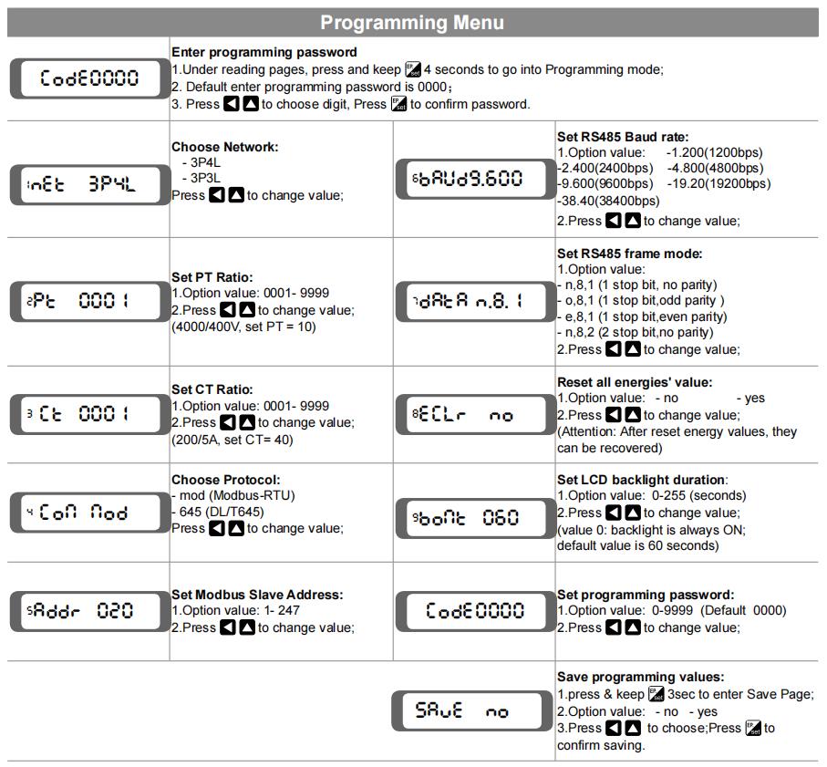
Step 2 Set CT ratio
Step 3 Solar Inverter grid connection
|
Inverter Error Code |
Anti-reflux meter communication |
04 |
01 |
A phase failure |
04-01 |
|
02 |
B phase failure |
04-02 |
|||
|
04 |
C phase failure |
04-04 |
|||
|
08 |
Meter communication failure |
04-08 |
|||
|
16 |
CT wiring failure |
04-16 |