1. System Power Consumption
As a start, it is important to consider the system power requirements, which usually involve the following parameters.
System load capacity calculation
If a set of system load types is as follows: lighting power 200W, power consumption 6h, washing machine power 400W, power consumption 3h, refrigerator power 135W, power consumption 24h, rice cooker power 400W, power consumption 3h, water heater 3200W.
Calculation of power consumption of conventional loads
Lighting: 200W*6=1.2kW-h
Electric rice cooker: 400W*3=1.2kW-h
We reserve daily electricity consumption of the washing machine and other kitchen loads for 3kW-h
→ Calculated 5.4kW-h
Calculation of power consumption for non-conventional loads
Refrigerators and electric water heaters are intermittent loads, and there are many factors affecting their daily power consumption, such as storage of food, start/stop times, and insulation performance of machine materials.
The power consumption of such loads should refer to their energy efficiency labels. For example, the nameplate of the energy efficiency label of the 135W refrigerator shows 0.69kW-h/24hm.
[Note] The rated power consumption refers to the power consumption in the environment of 25 degrees, refrigerator/freezer in a stable operating condition, not open the door empty box plugged into the power to run 24h, so the actual power consumption must be higher than this value.
According to the use- experience, the actual electricity consumption is about 1 time the label, which is 2kW-h a day, taking into account the loss of 3kW-h a day.
Electricity analysis of power 3200W electric water heater, according to the manufacturer's information about 1000W / 1h power consumption 1kW-h, 3200w * 1 = 3.2kW.h. According to the energy-saving signs, the standby insulation state is 0.6kW-h / 24h, and the total power consumption is 3.8kW-h, taking 4kW-h.
Total daily load power consumption
5.4kW-h+7kW-h=12.4kW-h. The above is the calculation of load power consumption, and it should be noted that the calculation idea is slightly different for conventional load and non-conventional load.2. Types of Loads
In the circuit, if there is a resistive inductor and capacitor, but the inductor and capacitor ratio is appropriate, the voltage and current can be the same phase, that is, "can be equivalent to pure resistance", such as the load for incandescent lamps, electric stoves, heaters, water heaters, electric ovens. In general, the purely resistive load that works only through resistive components is called resistive load.
Generally, the load with inductive parameters is called inductive load. To be exact, the load current should lag behind the load voltage a phase difference characteristic for inductive loads, such as transformers, motors, fans, washing machines, air conditioners, and other loads, called inductive loads. It refers to some equipment in the consumption of active power that also needs reactive power to establish the magnetic field. Circuits with coil loads are called inductive loads.
Capacitive load
Generally refers to loads with capacitive parameters, such as capacitors, and power compensation cabinets, i.e., loads that meet the voltage lag current characteristics. When the capacitive load is charged and discharged, the voltage cannot change abruptly and its corresponding power factor is negative, and the corresponding inductive load has a positive power factor.
System Configuration
1.Off-grid PV Capacity
We can infer the capacity of the PV system to be installed based on daily electricity consumption, considering the number of consecutive cloudy days, with local solar resources.
It is important to note that the design of the off-grid PV system here does not follow the design idea of an on-grid PV system design based on solar irradiance throughout the year. Changes in solar azimuth and altitude angle throughout the year result in different oblique irradiation reaching the PV module array.
2. Hybrid PV Capacity
Cost and installation area will take into account, and it will combine the capacity design with the customer's willingness to use utility power or diesel power in case of insufficient PV power generation. For the configuration of the diesel generator: the general diesel generator rated power range is 80%-120% * (photovoltaic storage inverter rated power), such as a three-phase energy storage inverter rated power 12kW, then the rated power of the diesel generator can be selected between 0.8 * 12kW = 9.6 kW ~ 14.4kW.
Selection of pure off-grid inverter
Industrial frequency off-grid PV inverter: The isolation transformer is located at the AC output and has a simple structure, high shock resistance, and large size and weight. The overload capacity of the IFT off-grid PV inverter is generally three times its rated power.
High-frequency off-grid PV inverter: The isolation transformer is located at the DC step-up side, which has strong adaptability, suitable for comprehensive loads, moderate cost, and carrying capacity. The overload capacity of a high-frequency off-grid PV inverter is generally two times its rated power.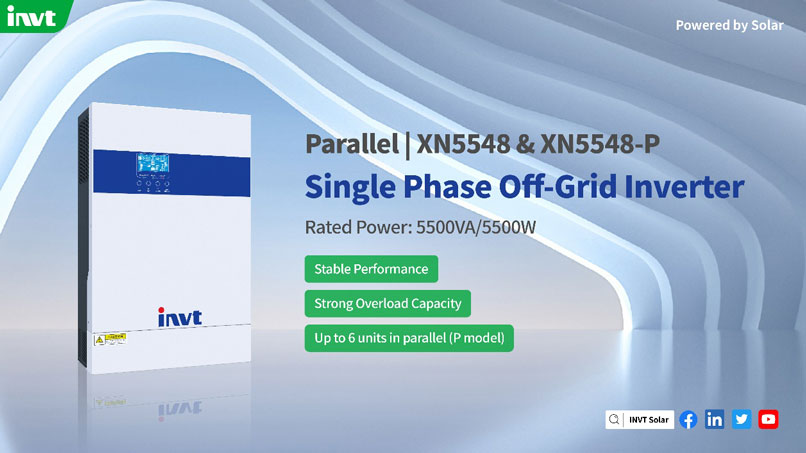
It is not recommended to choose a single-phase off-grid PV inverter for single-phase loads; although the inverter is powerful, most off-grid PV inverters do not have a three-phase balanced output, so single-phase loads may not be carried.
Off-grid PV inverter-rated capacity empirically takes the factor
For purely resistive household appliances like electric heaters, light bulbs, and sun lamps, divide its power by 0.9.
TV, for example, LCD, as long as the inverter can be 2 times larger than the power of the TV label.
Computer, according to the purchase of LCD TV point plus 90W power selection (computer host power).
Air conditioner, non-inverter by 7 times the peak count, inverter by 4 times the peak count.
Some small power appliances in the home can be ignored.
Calculation of off-grid PV inverter
Off-grid inverter rated power = load power * inverter margin factor/inverter power factor
Inverter maximum impact power P = resistive load power ÷ 0.9 + capacitive load power × 3 + inductive load power × (5~7)
Considering the load impact, and the overload capacity of the inverter can reach 1.5-2 times the rated power (100mS instantaneous), the inverter should at least withstand the maximum impact power Pmax, i.e. peak power: Pmax=P÷1.5
Inverter rated capacity Sn'= Pmax/cosθ (inverter power factor)
From the above formula, it is obtained that
200+400+135+400+3200=4,335*1.5/0.8=8,128.125
(200+3200)/0.9+(400+135)*7=3,777.77+3,745=
7,522.77/1.5=5015.18/0.8=6268.975VA
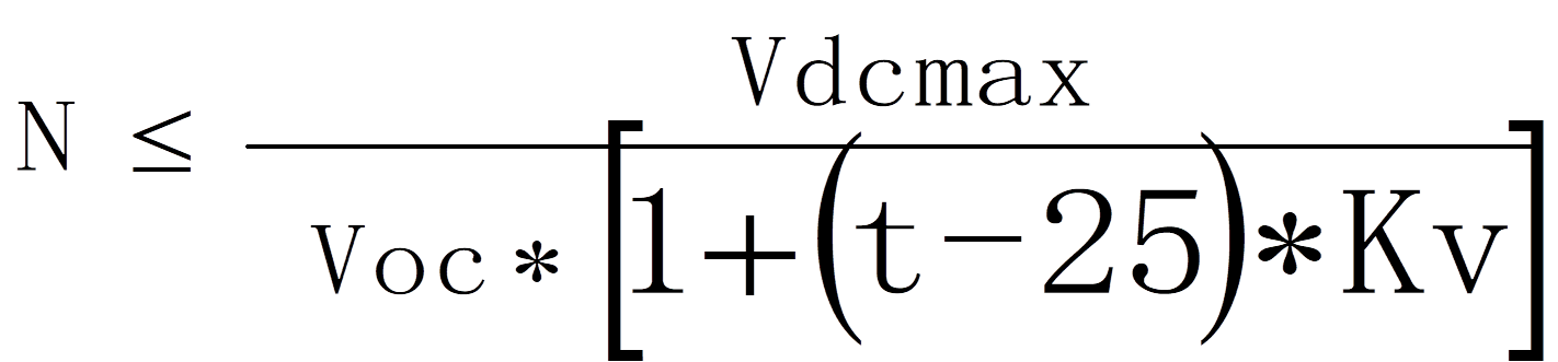
Matching components and inverters, according to the "PV power plant design specification" - GB50797, string calculation formula to calculate the number of strings in series.
Formula one: after taking into account the extremely low temperature of the project, the voltage of the components in series is within this range, and as close as possible to the rated input voltage of the inverter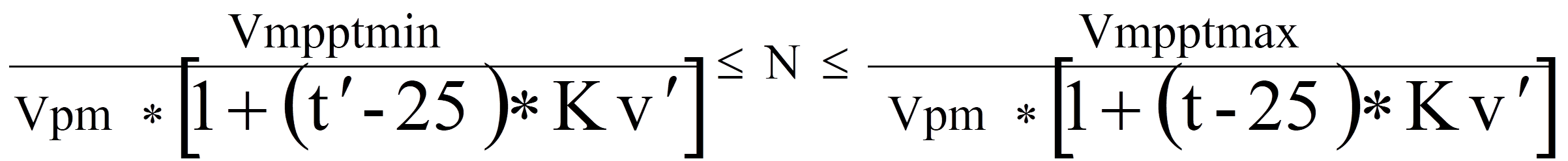
4. Battery Configuration
Battery capacity configuration
Configure the capacity of the energy storage battery according to the power of the load, power consumption, and the number of days of backup, focusing on the depth of discharge and the battery charging and discharging efficiency of the inverter: the depth of discharge of the battery, which indicates the percentage of the battery that has been discharged relative to the total battery capacity. The smaller the number, the more shallow the discharge. Over-discharge will lead to accelerated aging of the battery. When we choose the battery, the battery power indicated on the battery parameters is actually the theoretical power of the battery, and in practice, especially when the inverter is used in parallel, a DOD parameter is usually set to ensure that the system can operate normally. Usually, the termination voltage value is used to control the depth of discharge. The specific principle is that, as the battery is discharged, the battery voltage will be reduced by a small, when the battery voltage is lower than the set termination voltage, the discharge protection function is activated, and the discharge cut-off, to complete the control of the battery discharge depth. The depth of discharge of lithium iron phosphate batteries is generally controlled at about 80%, and lead-acid batteries are generally controlled at about 60%.
Battery charging and discharging efficiency refer to the efficiency of the battery terminals from the energy storage machine after boosting and inverting to the load side, which means that the load power supply is less than the amount of battery discharge. Therefore, when designing the battery capacity, if this efficiency value is not considered, it is likely to cause the phenomenon of insufficient battery power supply, especially in the case of off-grid backup power supply, battery power supply capacity = effective battery power * system efficiency %.
Battery Selection
In this case, the configuration of the battery capacity, for lead-acid batteries and lithium batteries configuration due to the depth of discharge of both on the PV system installed capacity impact is not the same.
Lead-acid battery selection configuration
Lead-acid battery, 12V/120AH, 12.4kW.h of daily power consumption, lead-acid battery is designed according to 60% discharge depth, so it needs 20.66kW.h of power backup. 12kW of PV is installed, and the average daily power generation is 23.77kW.h. 2 sets of 5kW off-grid PV inverters are used, each off-grid inverter is connected to 6kW of PV, and the daily power generation is 11.88kW.h. 11.88kW.h, access to 8 single batteries, using two series and one parallel storage power 11.52kW.h, access to the battery interface at the lower end of the off-grid inverter, forming a 48V battery power supply system. The entire off-grid system installed PV power of 12kW, a battery storage capacity of about 23.04kW.h. Battery power supply capacity, 23.04 * 0.93 = 21.42 kW.h> 12.4kW.h, to meet the electricity demand.
Lithium iron phosphate battery selection configuration
Choose a lithium iron phosphate battery, 3.2V/280AH, daily power consumption of 12.4kW.h, lithium iron phosphate battery by 80% depth of discharge, so the need for power backup is 15.5kW.h, then the PV installation capacity of 8kW, the use of 8kW off-grid PV inverter, lithium batteries to 15.5kW.h molding a PACK module, configuration battery BMS and battery protection board. Off-grid inverter docking communication protocol. The battery power supply capacity is 15.5*0.93=14.41kW.h>12.4kW.h to meet the power demand.
The design of this part of the off-grid PV system is simpler. Based on the area of PV installation for the design of PV installation capacity, according to the power generation, configure reasonable battery capacity and set the better working mode.